Instructions:
1. insert the lcd screen into the row I, and align the silver notches on the side so they are plugged into I 30-15
2. put the push button on. Make it so the prongs are at c 3, c5, and f 3, and f 5.
3. put the potentiometer on. Make the prongs go into c16, c15, and c14
4. put the RGB LED into c10, c9, c8, and c7
5. put a wire running from the GND to the negative at the very top left on the board.
6. put a wire running from 5V to the positive at the top left of the board.
7. put a wire running from A1 to a14, next to the potentiometer.
8. put a wire on the negative on the very bottom left of the board, running to f30
9. put a wire running from the positive on the 2nd to last row on the left, to f29
10.put a wire running from the negative on the 3rd to last row on the left, to f26
11.put a wire running from E14, to the positive on the 2nd row on the left.
12.put a wire running from f28, to E15
13.put a wire running from E16, to the negative on the 8th row down on the left.
14.put a wire running from F27, to pin 12
15.put a wire running from F25, to pin 11
16.put a wire running from F20, to pin 5
17.put a wire running from F19, to pin 4
18.put a wire running from F18, to pin 3
19.put a wire running from F17, to pin 2
20.put a wire running from F16, to the positive on the 12th row down on the left.
21.put a wire running from F15, to negative on the 11th row down on the left.
22.put a wire running from H10, to pin 0
23.put a wire running from H8, to pin 7
24.put a wire running from H7, to pin 13
25.put a wire running from D9, to the negative on the 6th row down on the left
26.put a wire running from B5, to pin 8
27.put a wire running from A3, to the negative on the 4th row down on the left.
28.put the resistor (brown, orange, orange) in the positive on the 5th row down on the left, to B4
29.put another one of the same resistors in D7, to G7
30.put another one of the same resistors in D8, to G8
31. put another one of the same resistors in D10, to G10
32.that is all the steps to completing the wiring!
Troubleshooting Guide:
Button not working?
1. Make sure it is connected to pin number 8.
2. Make sure that there is a 3k ohm resistor with one end of the resistor connected to the positive column of the breadboard and the other connected to the button.
3. Make sure that the button is connected across the breadboard and is not on only one side of the breadboard.
LCD not working?
1. Fully rotate the potentiometer.
2. Make sure that the LCD is connected to pin numbers 12, 11, 5, 4, 3, 2.
3. Make sure that there is a wire connecting the potentiometer and the LCD screen.
RGB not working?
1. Make sure that red is connected to pin number 0, green is contected to pin number 7, and blue is connected to pin number 13.
2. Make sure that the button is properly wired and connected to the positive column of the breadboard with a 3k ohm resistor.
Potentiometer not working?
1. Make sure that the potentiometer is hooked up to pin number A1.
2. Make sure that there is a wire connecting the LCD and the potentiometer.
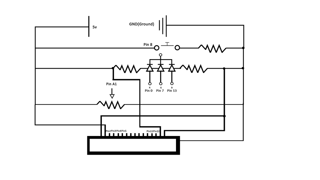
Schematic:
Code:
#include <LiquidCrystal.h>
LiquidCrystal lcd(12,11,5,4,3,2); //Pin numbers for lcd screen
const int buttonPin = 8; //Pin number for button
const int potPin = A1; //Pin number for potentiometer
const int Red = 0; //Pin number for red light RGB
const int Green = 7; //Pin number for green light RGB
const int Blue = 13; //Pin number for blue light RGB
int potVal = 0; //Stores the potentiometer value
int buttonState = 0; //Stores if button is on or off
void setup()
{
pinMode(buttonPin, INPUT); //Create button pinMode
pinMode(Red, OUTPUT); //Create red light pinMode
pinMode(Green, OUTPUT); //Create green light pinMode
pinMode(Blue, OUTPUT); //Create blue light pinMode
}
void loop()
{
potVal = analogRead(potPin); //Read the potentiometer for value
buttonState = digitalRead(buttonPin); //Read button for value
lcd.begin(16, 1); //Begin printing lcd + plus coordinates to print
lcd.clear(); //Clear screen before printing
lcd.print(potVal); //Print potentiometer value
lcd.setCursor(0,1); //Set cursor for lcd
lcd.print(millis()/1000); //Set how long it takes for lcd to print
//If and else statement controlling RGB color
if(buttonState == HIGH)
{
analogWrite(Red, potVal);
analogWrite(Green, 0);
analogWrite(Blue, 0);
}
else {
analogWrite(Red, 0);
analogWrite(Green, potVal); //Make blue light RGB turn on if button is not being pressed
analogWrite(Blue, 0);
}
}
